LINK Kiosk Hardware Set-up Guide
For video instruction: https://www.youtube.com/watch?v=8emUmWXlSx4
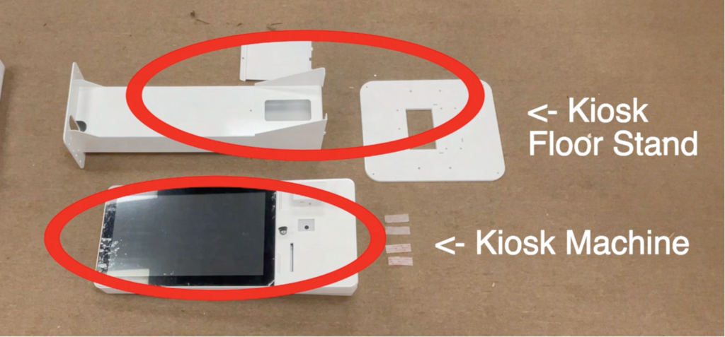
- Kiosk and Stand parts
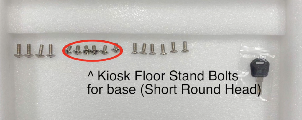
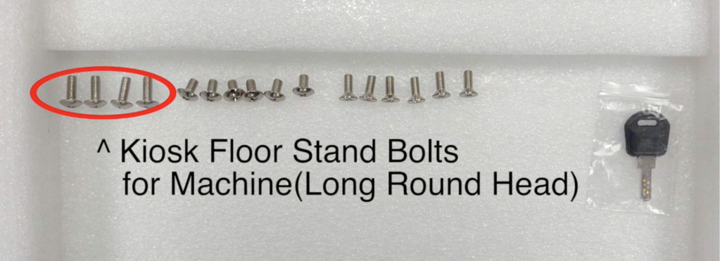
- Bolts needed.
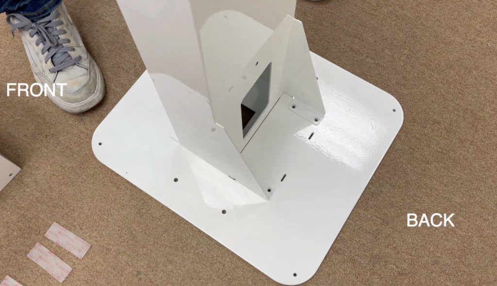
- Kiosk Floor Stand Base
This is very heavy panel. Bolts will be screwed in into these 6 circled holes.

- Place stem on top of base. Holes on the stem should align holes on the panel.
- Short, Round Head bolts will be used to fasten. There will be only 6 provided so make sure to screw into circled spots above.

- Bolts placement front and back


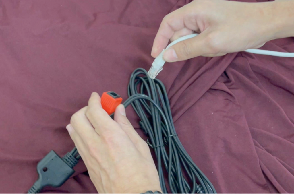
- Kiosk machine will be sent with LAN cable and Power cable already attached to the machine.

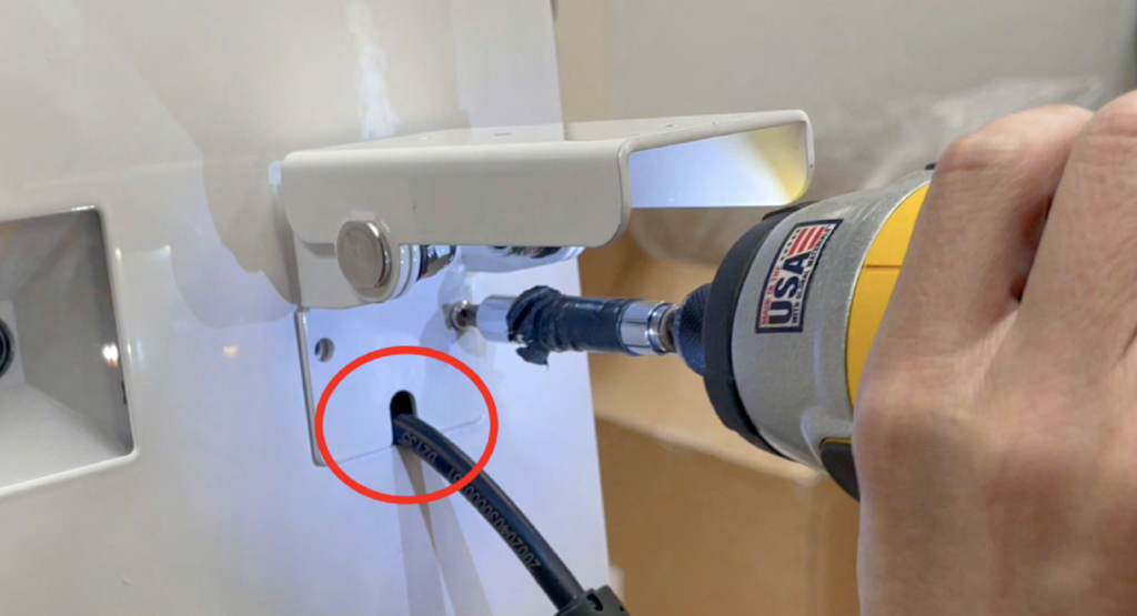
- You can use the hole to hide LAN and power cable if needed. It could go through the hole at the bottom of stand stem too.
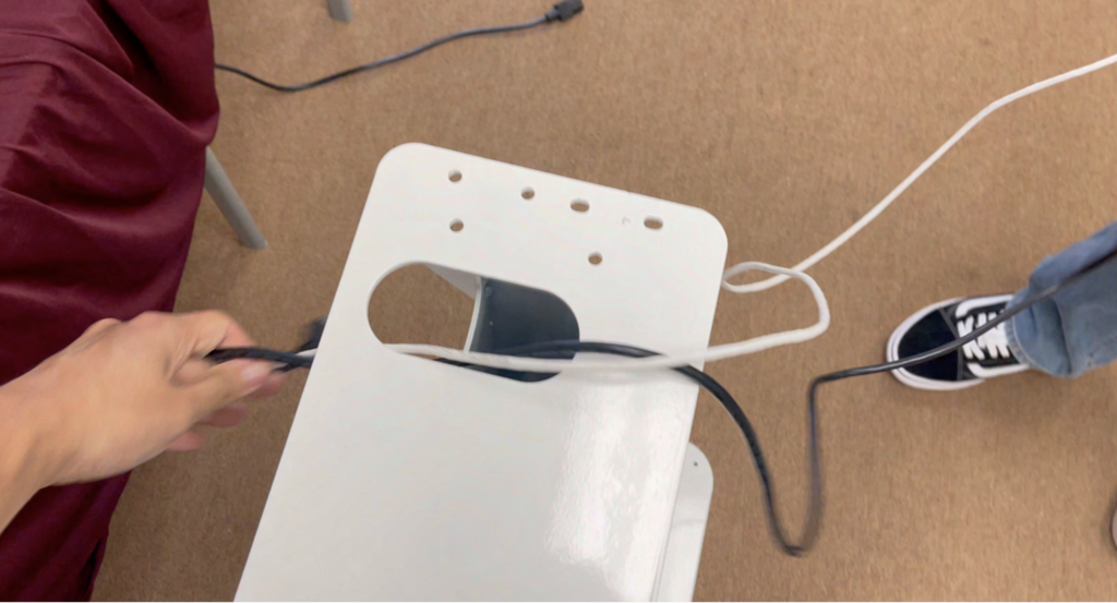
- The hole in Kiosk and Hole on top base of stem should be aligned.
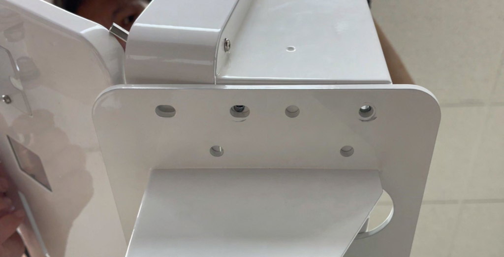
- 4 Long, Round Head bolts should be screwed in. (2 on each side)
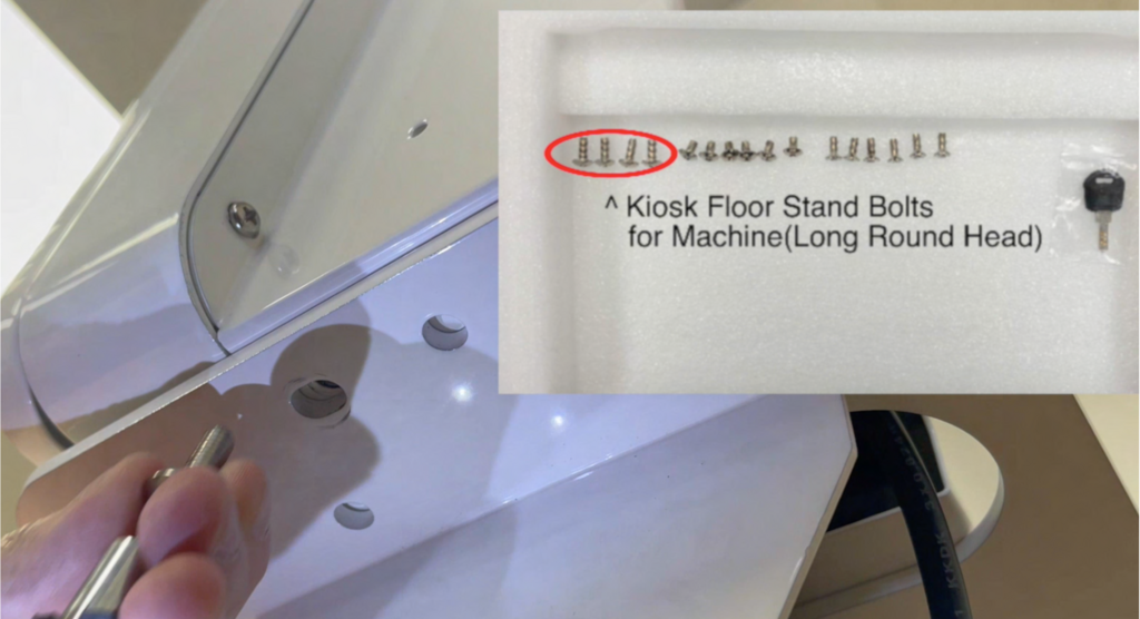

- That should be it for structure assembly.
Card Terminal Assembly
- Card terminal assembly should be the next one.
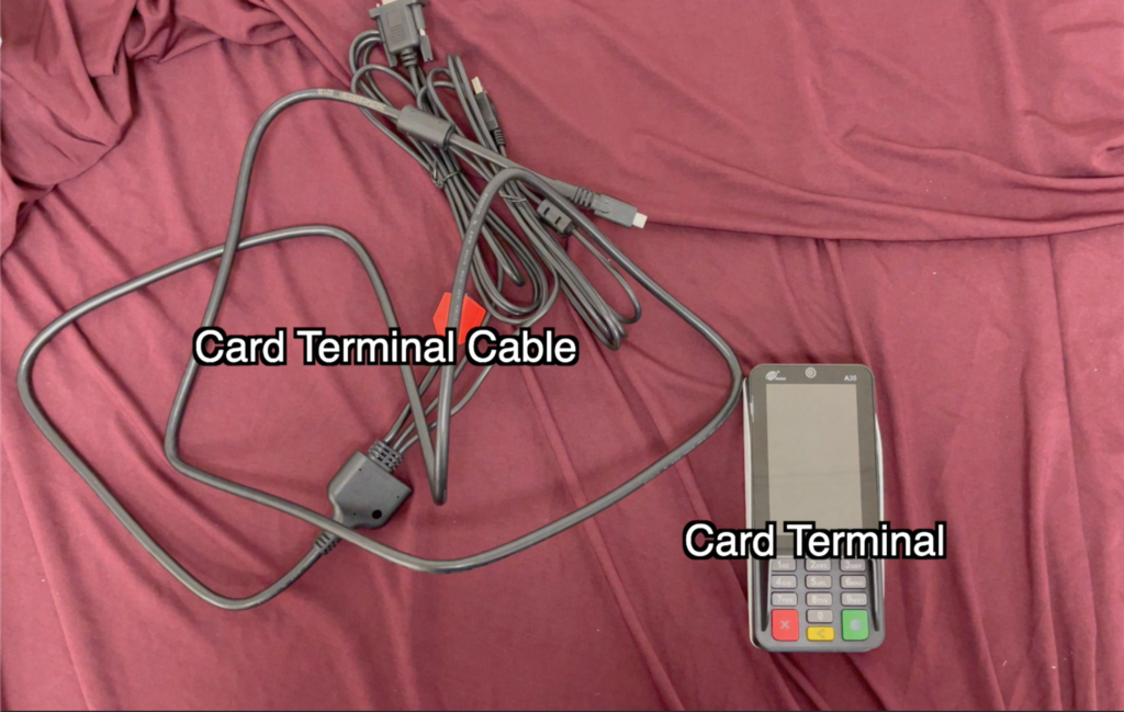
- LAN Cable should be connected to RED and to the router. (2 LAN cables should be connected individually to Kiosk and Terminal)
13-1. Power for Card terminal will be connected via USB to USB-C cable. Please connect it to USB power supply.

- To connect the Card Terminal Cable, please open the Kiosk case.

- Please unscrew the Card Terminal Pinpad mount. There will be one bolt from inside the case, and another 2 from outside the case.

- Here’s another 2 bolts from outside.

- Let the USB-C cable head towards the front of the kiosk through hole in the back.
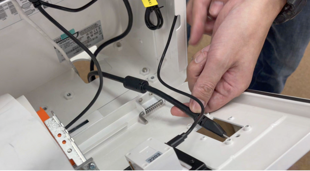
- Reattach the mount. Let the cable run through a little gap in the mounting bracket.
- Unscrew back of card terminal and take off the back panel.

- Connect USB-C cable to the card terminal. Make sure the wedged part goes on top.

- Make sure the cover is placed in the right place.

- Please screw cover back into place

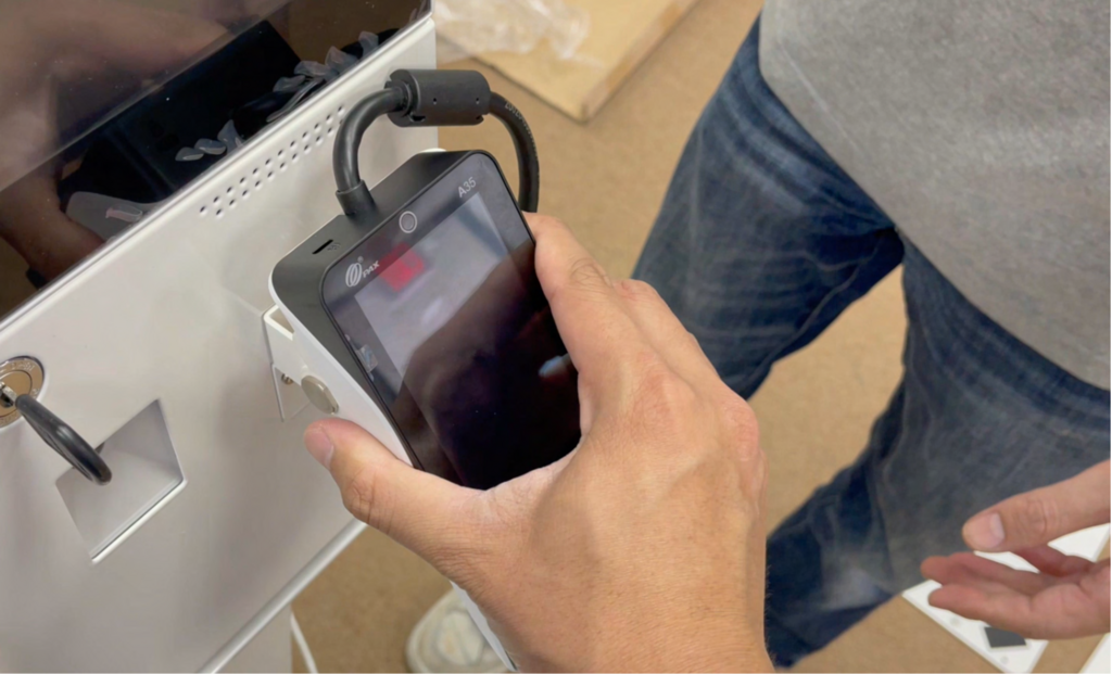
- Pull the film of the fastener strip, and attach the card terminal on top.

- Attach anyway you want.
- To turn on, press power button inside the case on left front corner.